
Pentre Group
For all your packaging & process solutions
Pentre Group
For all your packaging & process solutions
High Performance ABS Flanged Process Reels – Telephone Cable are at the forefront of manufacturing technology. Developed specifically for use with telecom, data and communication
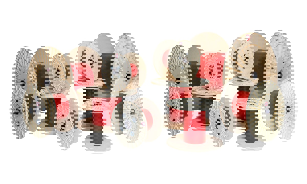
Hearl Heaton High Performance ABS Flanged Process Reels – Telephone Cable are at the forefront of manufacturing technology. Developed specifically for use with telecom, data and communication cables, they are available in both metric and imperial sizes from 350mm to 1000mm and 12” to 22. Reels are manufactured to DIN 46395 as standard or bespoke customer requirements.
Capable of operating to extrusion speeds of up to 2,500mpm (metres per minute) makes them ideal for use as take-up reels across a range of applications, but in particular high speed telephone core extrusion lines and subsequent cable manufacturing, single and doubletwist machines, group twinners stranding, bunching, quading and laying up.
Suitable for use across a wide range of products including:
Flanges are moulded from Pentre’s own specially selected, high grade, virgin Acrylonitrile Butadiene Styrene (ABS), which combines strength with lightness, without becoming brittle.
For additional strength barrels are usually manufactured from seam welded, painted mild steel and the CNC machined bosses engineered from mild steel. Reels are secured using high tensile strength steel bolts and unique locknuts. The precision manufactured parts and construction ensures that the reels are in balance for high speed applications. Our reels are suitable for reel handling systems.

|
|
|
| Product Type | d1 | d2 | d3 | d4 | d5 | e1 | L1 | L2 | Vol. |
|---|---|---|---|---|---|---|---|---|---|
| PFTC400 | 400 | 160 | 73 | 56 | 16-28 | 112 | 300 | 250 | 26 |
| PFTC400 | 400 | 200 | 73 | 56 | 16-28 | 112 | 236 | 200 | 19 |
| PFTC450 | 450 | 224 | 73 | 56 | 16-28 | 112 | 265 | 224 | 27 |
| PFTC500 | 500 | 200 | 73 | 56 | 16-28 | 140 | 375 | 315 | 52 |
| PFTC500 | 500 | 250 | 73 | 56 | 16-28 | 140 | 300 | 250 | 37 |
| PFTC560 | 560 | 280 | 73 | 56 | 16-28 | 140 | 335 | 280 | 52 |
| PFTC630 | 630 | 250 | 73 | 56 | 16-28 | 140 | 475 | 400 | 74 |
| PFTC630 | 630 | 315 | 73 | 56 | 16-28 | 140 | 375 | 315 | 74 |
| PFTC800 | 800 | 400 | 98.5 | 80 | 28-40 | 160 | 600 | 500 | 188 |
| PFTC1000 | 1000 | 500 | 98.5 | 80 | 28-40 | 160 | 750 | 630 | 371 |
|
|
|
| d1 | d2 | s1 |
|---|---|---|
| 350 | 180 | 12.0 |
| 400 | 152 | 17.0 |
| 400 | 160 | 17.0 |
| 400 | 200 | 17.0 |
| 400 | 203 | 17.0 |
| 400 | 229 | 17.0 |
| 406 | 160 | 12.7 |
| 406 | 201 | 20.6 |
| 450 | 150 | 20.5 |
| 450 | 203 | 20.5 |
| 450 | 224 | 20.5 |
| 450 | 229 | 20.5 |
| 450 | 170 | 27.5 |
| 450 | 203 | 27.5 |
| 450 | 224 | 27.5 |
| 450 | 250 | 27.5 |
| 457 | 224 | 20.7 |
| 490 | 152 | 17.0 |
| 490 | 250 | 20.0 |
| 490 | 265 | 20.0 |
| 500 | 200 | 20.0 |
| 500 | 247 | 20.0 |
| 500 | 250 | 20.0 |
| 500 | 260 | 20.0 |
| 500 | 280 | 20.0 |
| 500 | 250 | 27.5 |
| 500 | 280 | 27.5 |
| 560 | 250 | 20.0 |
| 560 | 280 | 20.0 |
| 560 | 203 | 27.5 |
| 560 | 250 | 27.5 |
| 560 | 260 | 27.5 |
| 560 | 280 | 27.5 |
| 600 | 250 | 25.0 |
| 600 | 300 | 25.0 |
| 600 | 315 | 25.0 |
| 600 | 355 | 25.0 |
| 630 | 250 | 25.0 |
| 630 | 300 | 25.0 |
| 630 | 315 | 25.0 |
| 630 | 355 | 25.0 |
| 800 | 400 | 40.0 |
| 1000 | 500 | 40.0 |
Please Note
Most bore diameters (d4) accommodated, maximum size dependent on each flange configuration
All drive holes, pin diameters (d5) and positions can usually be tailored to suit your exact requirements
The overall width (L1) must be at least the traverse width (L2) + 2 x flange width (s1)
|
|
|
| d1 | d2 | s1 |
|---|---|---|
| 12 | 6 | 11/32 |
| 16 | 6 | 1/2 |
| 16 | 8 | 1/2 |
| 16 | 6 | 11/32 |
| 16 | 8 | 11/32 |
| 16 | 6 | 13/16 |
| 16 | 8 | 13/16 |
| 16 | 9 | 13/16 |
| 18 | 6 | 13/16 |
| 18 | 8 | 13/16 |
| 18 | 9 | 13/16 |
| 18 | 9 | 1 |
| 20 | 8.5 | 1 |
| 22 | 10 | 25/32 |
| 22 | 11 | 25/32 |
Please Note
Most bore diameters (d4) accommodated, maximum size dependent on each flange configuration. All drive holes, pin diameters (d5) and positions can usually be tailored to suit your exact requirements
The overall width (L1) must be at least the traverse width (L2) + 2 x flange width (s1)
Browse related products below, or complete our simple online enquiry form and one of our highly experienced product specialists will be in touch.


